Project 3: Hydrofracturing and localized venting above sill intrusion?
Project objectives
Explore under which conditions hydrofracturing leads to localized venting
Implement a pressure-dependent permeability
Interpret the results in the context recent papers.
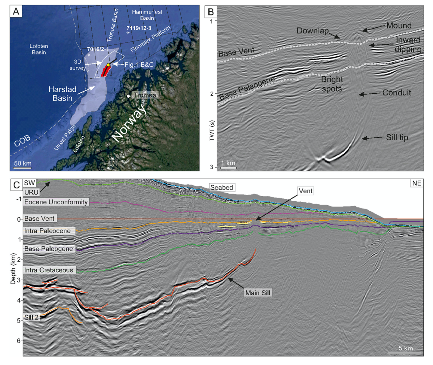
The third exercise is very similar to the second exercise in that we will explore hydrothermal circulation systems driven by a magmatic heat source. Seismic data has revealed pipe-like structures leading up from the tips of sheet-like magmatic intrusion towards the paleo-seafloor. It remains, however, poorly understood how these pipe-like strutures form. Recent modeling papers have used a pressure-dependent permeability to mimic hydrofracturing [Aarnes et al., 2010] [Iyer et al., 2017] [Weis et al., 2012]. The underlying idea is that heating of pore fluids results in fluid expansion, which increases the fluid pressure, which is eventually released by hydrofracturing. Here we will explore these processes!

Fig. 57 Figure taken from [Iyer et al., 2017] on sill intrusions and hydrothermal venting in sedimentary basins.
Technical background
The feedbacks between fluid pressure and mechanical deformation is a vast field and way beyond the scope of this lecture. We will here only explore a highly simplied, yet useful and instructive case. More concrete, we will look how fluid pressure can induce hydrofracturing and thereby permeability creation. We will exemplify this for the example of sill intrusions into low permeability sediments.
In a nutshell, coupling between fluid flow and mechanics naturally results in the Terzaghi’s concept of effective stress:
Fluid pressure is deducted from the total stress resulting in effective stress. In terms of pressure, this implies that the effective pressure a rock “feels” can be lowered by fluid overpressure thereby facilitating failure. Think of dehydration reactions and intermediate depth earthquakes in subduction zones.
Speaking of failure, rocks can fail in two major modes: brittle shear failure or extensional tensile failure (mode I cracks). Those failure modes occur when the differential stress exceeds one of the yield stresses:
where \(\tau\) is the differential stress, \(\sigma^{\prime}_{m}\) is the effective mean stress (pressure), \(C\) cohesion, \(\sigma_{T}\) tensile strength. Draw a Mohr circle to check that you understand this! There is also a nice paper by [Cox, 2010] with more details on this.
Things are a bit more complicated than this with feedbacks between fluid pressure and stress state but this gives the basic picture. Have a look at [Rozhko et al., 2007] for more details.
Technicalities
Solver changes
We have to make the same modifications as in project 2 in that we need to account for the latent heat of crystallization. We again do this by using an effective specific heat for the solid phase in the energy equation (see e.g. [Aarnes et al., 2010]):
In addition, we need to implement a pressure-dependent permeability according to the mechanical feedbacks given above. We will make the simplifying assumption that the sedimentary basin is not “pre-stressed”, i.e. we do not impose a pre-existing differential stress profile as in [Weis et al., 2012] . We simply assume that permeability is progressively increased when the fluid pressure exceeds the lithostatic pressure (a very simple fracture criterion). This permeability model is described in [Iyer et al., 2017] and in [Galerne & Hasenclever, 2019].
Here \(p_l\) is the lithostatic pressure, the weight of the overburden. \(k_{eff}\) shows up on both sides of the equation, which mimics progressive crack/vein oppening.
In addition, we will impose depth-dependent porosity and permeability profies according to [Iyer et al., 2017].
where y is in kilometers.
These changes are implemented in a modified solver of HydrothermalFoam, which you can download from here (HydrothermalSinglePhaseDarcyFoam_p_k).
Check the updateProps.H and 0/permeability.org and 0/porosity files, how these changes are implemented.
Setup fields
In addition to the solver changes, we have to take extra care of the initial conditions. The temperature field is not uniform anymore but we need to set the initial intrusion temperature to a high value according to its cellzone and apply a background temperature gradient (if we think that’s useful).
These changes are implemented as codestream statements in 0/T . Have a look!
Deliverables
The goal of this project is to provide work on these topics
Conditions for localized venting, provide a sequence of 2D simulations that illustrate what can “happen” for host rock permeabilities.
Mechanism, investigate the driven mechanism in that you visualize the pressure field and how it affects permeability.
Systematics, explore the parameter space.
The results showed be delivered in a short powerpoint presentation.
Starting point
Case file
Download the basic case file from (Sill intrusion Flow Model).. It includes a basic setup for hydrothermal system drive.
Meshing software
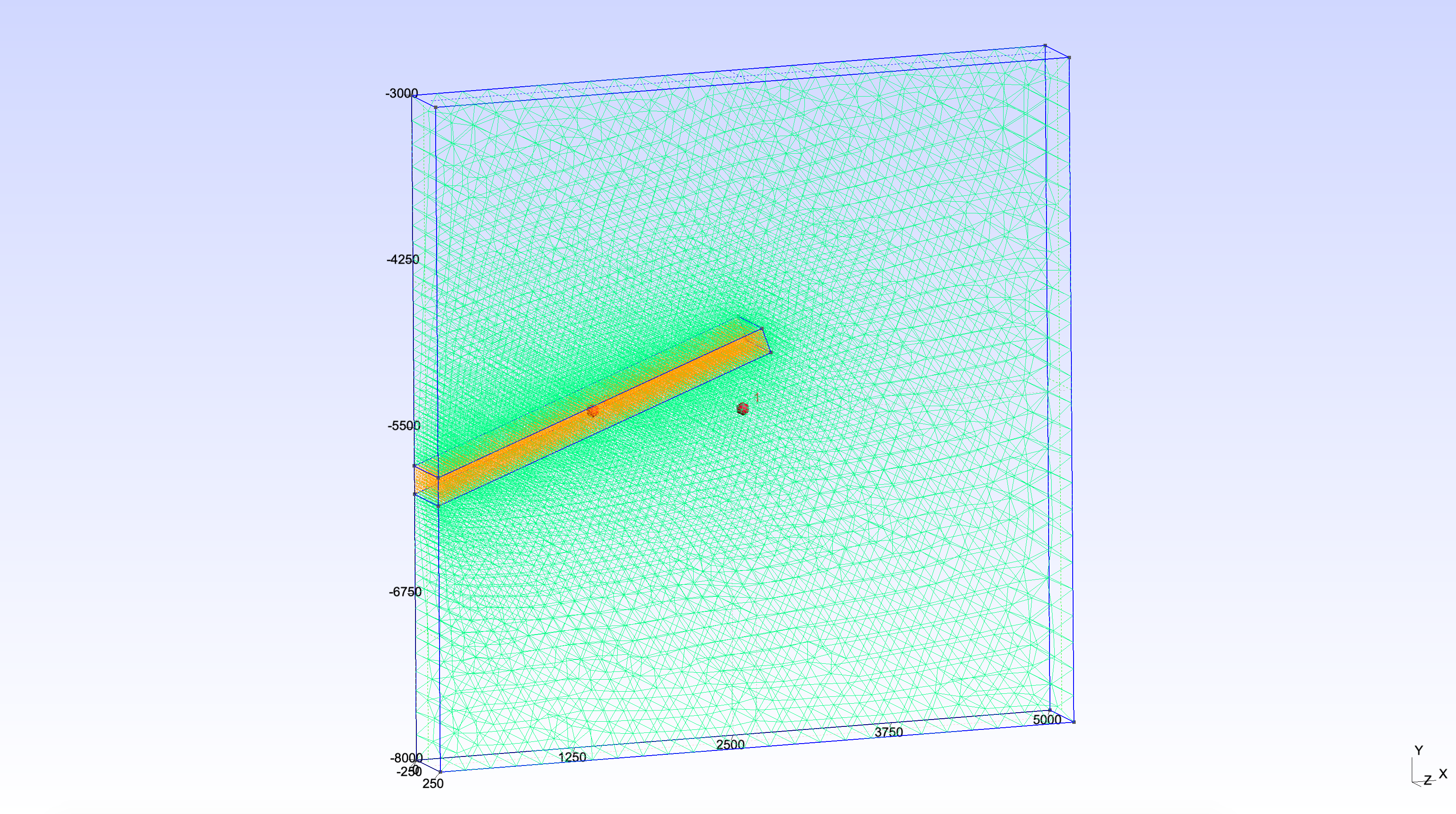
The example case uses a meshing software called Gmsh to create a mesh that resolves the fault zone. Gmsh is already installed within your docker containers, so there should be no need for installing additional software. The gmsh input file is in gmsh/make_mesh.geo.

Fig. 58 Mesh created with gmsh.
Have a look at gmsh/make_mesh.geo and the Gmsh . Check that you (more or less) understand what’s happening and try to change things like fault width and and angle.
Post-processing
There are many ways of extracting information from a completed run. For this project, you will want to know how high the vent temperature is and where the venting occurs, so that you can evaluate if the plume was “captured” by the fault. You can either do this in paraview by using, for example, the “Plot Over Line” filter in Paraview. An alternative is to use the built-in postprocessing function of OpenFoam.
Also check the system/controlDict.orig file; there is codestream section at the bottom that writes out maximum vent temperature to a file names ventT.txt . Modify according to your needs.
postProcess -func sampleDict -latestTime
It will read the system/sampleDict file (have a look!) and extract T along a line.
More powerful is, of course, to use python, like in Upflow temperatures in submarine hydrothermal systems.
Background reading
[Weis et al., 2012] paper on the pressure dependent permeability
[Aarnes et al., 2010] [Iyer et al., 2017] [Galerne & Hasenclever, 2019] paper on modeling sill intrusion into sedimentary basins
[Svensen et al., 2004] landmark paper on the relationship between sill intrusion into organic sediments, greenhouse gas relase, and climate change as well as mass extinctions.