Flow on the pore scale
Objective
Starting from a digital representation of a sample’s pore space (typically an image produced by a cT-scan), we want to compute the permeability of the sample. Put differently, we will make a direct simulation of flow on the pore level and post-process it for extracting the permeability to be used, for example, in simplified continuum simulations using Darcy’s law.
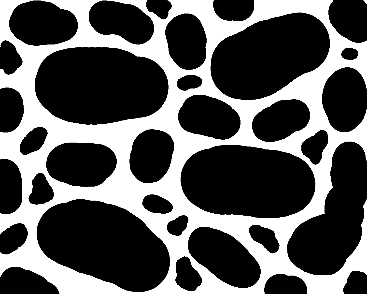
Fig. 12 Synthetic image of the pore geometry. Pores are white; solids are black.
To compute permeability, we will apply constant pressure boundary conditions and evaluate the flow rate through the sample. Once we have that, we can re-arrange Darcy’s law to solve for permeability:
Ok, let’s do it!
Mesh generation
The first major step is to generate a mesh of the pore space (Fig. 12). For this purpose, we will use OpenFOAM’s snappyHexMesh tool. It allows meshing arbitrary and complex geometries and is very powerful. Unfortunately, it can also be infuriating to use as it asks for many user-defined parameters and can be quite picky about the choices made.
Tip
We will not go into the details of how snappyHexMesh (SHM) works. If you want to use and/or understand it, a good starting point is the user guide linked above. Another great resource is the Rock Vapor Classic tutorial series.
In a nutshell, snappyHexMesh (SHM) is about starting from a blockMesh (as in the previous lecture), cutting out the solid grain (described by a triangulated surface), and then snapping the mesh to this surface. A typical way to describe this surface is an .stl file - a file format for triangulated surfaces that is often used for 3D printing.
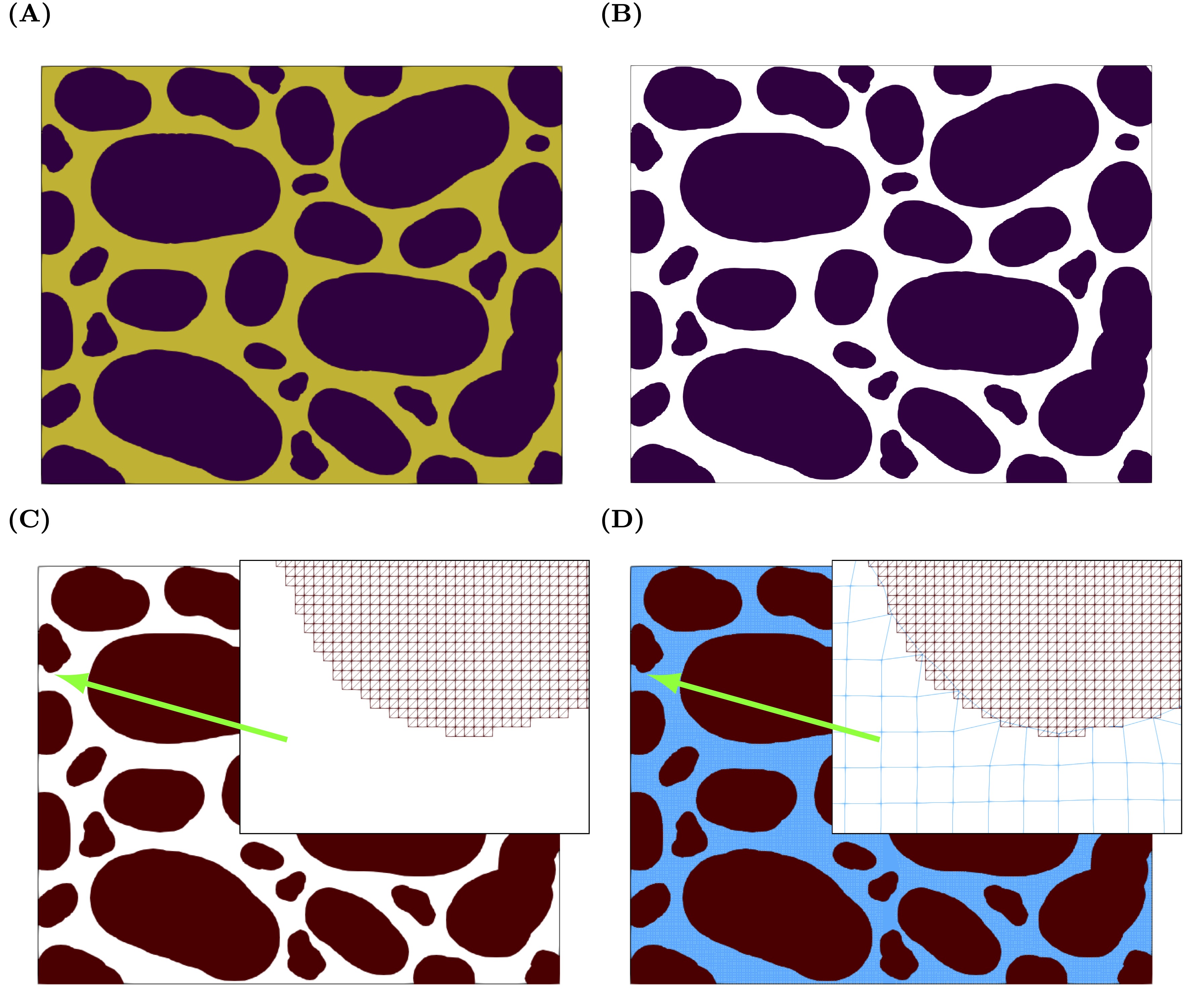
Fig. 13 Workflow illustrating the meshing process.
The steps involved are shown in Fig. 13 . Starting from an image, an stl file is created that is then used during the meshing process. Most of the steps will rely on paraview filters and the workflow is this.
Start with an image (A).
Save it as a .vti file that is easily understood by Paraview. We use porespy for this step.
Load the vti file into paraview and use the clip (B) and triangulate (B) filters to create a surface of the solid grains (C).
Save this surface as an stl file.
Python pre-processing
Let’s work through the steps involved and assume we received a 2-D image of scanned pore space ( Fig. 13 A). We need to translate it into something that Paraview understands, so that we can do the segmentation and surface generation. We will use porespy for it, which is already installed in the course container (together with PIL, which is also needed).
Now we are good to go and it’s time to download the data. The complete openFOAM case can be downloaded from here .
Copy the case into your shared working directory $HOME/HydrothermalFoam_runs. You need to do this within the docker container, i.e. in a terminal in Visual Studio Code.
Check out the directory structure shown in Listing 14.
.
├── 0
│   ├── U
│   └── p
├── a.foam
├── clean.sh
├── constant
│   ├── transportProperties
│   ├── triSurface
│   └── turbulenceProperties
├── geometry
│   └── porousModel.png
├── run.sh
└── system
    ├── blockMeshDict
    ├── controlDict
    ├── fvSchemes
    ├── fvSolution
    ├── meshQualityDict
    └── snappyHexMeshDict
Tip
Most OpenFoam cases include scripts like run.sh and clean.sh. The run.sh script is a good starting point for “understanding” a case. It lists all commands that have to be executed (e.g. meshing, setting of properties, etc.) to run a case. The clean.sh script cleans up the case and deletes e.g. the mesh and all output directories. Have a look into these files and see if you understand them!
Next we import the .png file from the geometry folder and convert it to a .vti file, which is the Visualization Toolkit’s format for storing image data. Note that vti files can also store series of images, which is important when doing this in 3-D.
import numpy as np
from PIL import Image
import porespy as ps
import os

impath = './geometry'         # image path
imname = 'porousModel.png'   # file name

# 1. use PIL to load the image
# convert("L") converts RGB into greyscale, L = R * 299/1000 + G * 587/1000 + B * 114/1000
image = Image.open(os.path.join(impath, imname)).convert("L")

# 2. convert image into numpy array with "normal" integer values
arr = np.asarray(image, dtype=int)

# 3. save as vti (VTK's image format)
# 3.1 make 3D by repeating in new axis=2 dimension (openfoam and porespy want 3D)
arr_stacked = np.stack((arr,arr), axis=2)

# 3.2 save as vti using porespy
ps.io.to_vtk(arr_stacked, 'geometry/porous_model')
You can put this little script into a jupyter notebook or save it as .py (e.g. png2vti.py) and run it in a terminal in the container:
python png2vti.py
After running it, you should have a file porous_model.vti in the geometry folder.
Tip
If you are interested in the vti file format: the file is too large to open in the editor (about 28 MB), because the image data is stored in binary form. But the first lines are plain text and describe the data. Show them in the terminal:
head -n 9 geometry/porous_model.vti
<?xml version="1.0"?>
<VTKFile type="ImageData" version="1.0" byte_order="LittleEndian" header_type="UInt64">
<ImageData WholeExtent="0 1196 0 1494 0 2" Origin="0.0 0.0 0.0 " Spacing="1 1 1 ">
<Piece Extent="0 1196 0 1494 0 2">
<CellData Scalars="im">
<DataArray Name="im" NumberOfComponents="1" type="Int64" format="appended" offset="0"/>
</CellData>
</Piece>
</ImageData>
Notice how the image is written as cell data with the name im. The extents count points: 1197 x 1495 x 3 points enclose 1196 x 1494 x 2 cells, i.e. one cell per pixel of our two stacked images, and the voxel size (Spacing) is 1. format="appended" means that the actual values (0 or 255 for every pixel) follow after this header as raw binary data, which is why the file looks like garbage after these lines.
Making the stl file in ParaView
Now comes the segmentation: we separate the grains from the pores and turn the grains into a triangulated surface, an stl file that openFOAM understands. We do this in ParaView, which runs on your computer, so all files are in the case directory in the HydrothermalFoam_runs folder of your course folder.
First, create the folder that will hold the stl file. In a terminal in the container, in the case directory, type:
mkdir -p constant/triSurface
Then follow these steps in ParaView:
Open the image. File → Open, select
geometry/porous_model.vtiand click Apply. You see the image as a gray-scale picture; color it byimif it is not colored yet. Pores have the value 255 (white), grains the value 0 (black).Cut out the grains. Select
porous_model.vtiin the Pipeline Browser and apply Filters → Alphabetical → Clip. In the Properties panel, setClip Type to
Scalar,Scalars to
im,Value to
127.5, halfway between pores and grains,leave Invert ticked, so that the cells with values below 127.5, the grains, are kept,
and click Apply. Only the grains are left.
Make a surface. Apply Filters → Alphabetical → Extract Surface to the clip, and click Apply.
Triangulate it. Apply Filters → Alphabetical → Triangulate to the surface, and click Apply. The stl format can only store triangles.
Save it. Select the
Triangulatefilter, choose File → Save Data, select the file type STL, and save it asporous_model.stlin the folderconstant/triSurfaceof your case. ParaView then asks for two options: keep File Type atBinary(the file is much smaller than in ASCII, and OpenFOAM reads both), and leave Choose Arrays To Write unticked (an stl file only stores the surface triangles, no data). Click OK.
Check that the file constant/triSurface/porous_model.stl exists. That’s it: the geometry is ready for meshing.
Optional: the same steps as a Python script
Clicking through the filters becomes tedious if you have to do it for many images, e.g. in the exercise with random disk packings. ParaView can also be controlled with Python, and the following script does exactly the steps above. Save it as make_stl.py in your case directory.
# make_stl.py: segment the image and save the grains as stl file
from paraview.simple import *
import os

vti_file = 'geometry/porous_model.vti'              # input image
stl_file = 'constant/triSurface/porous_model.stl'   # output surface, where OpenFOAM expects it

data          = OpenDataFile(vti_file)                                       # 1. open the image
clip          = Clip(Input=data, ClipType='Scalar', Scalars=['CELLS', 'im'],
                     Value=127.5, Invert=1)                                  # 2. keep the grains
surface       = ExtractSurface(Input=clip)                                   # 3. make a surface
triangulated  = Triangulate(Input=surface)                                   # 4. triangulate it
os.makedirs(os.path.dirname(stl_file), exist_ok=True)
SaveData(stl_file, proxy=triangulated)                                       # 5. save it
To run it, open the Python shell in ParaView (View → Python Shell, Fig. 14), change into your case directory, and execute the script:
import os
os.chdir("/path/to/your/HydrothermalFoam_runs/DRP_permeability_2D")
exec(open("make_stl.py").read())
You can also run it without opening ParaView, with pvpython, ParaView’s own Python, from a terminal on your computer (not in the container), in the case directory:
# macOS (adjust the version number)
/Applications/ParaView-5.13.2.app/Contents/bin/pvpython make_stl.py

# Windows, in PowerShell (adjust the version number)
& "C:\Program Files\ParaView 5.13.2\bin\pvpython.exe" make_stl.py

# Linux
pvpython make_stl.py
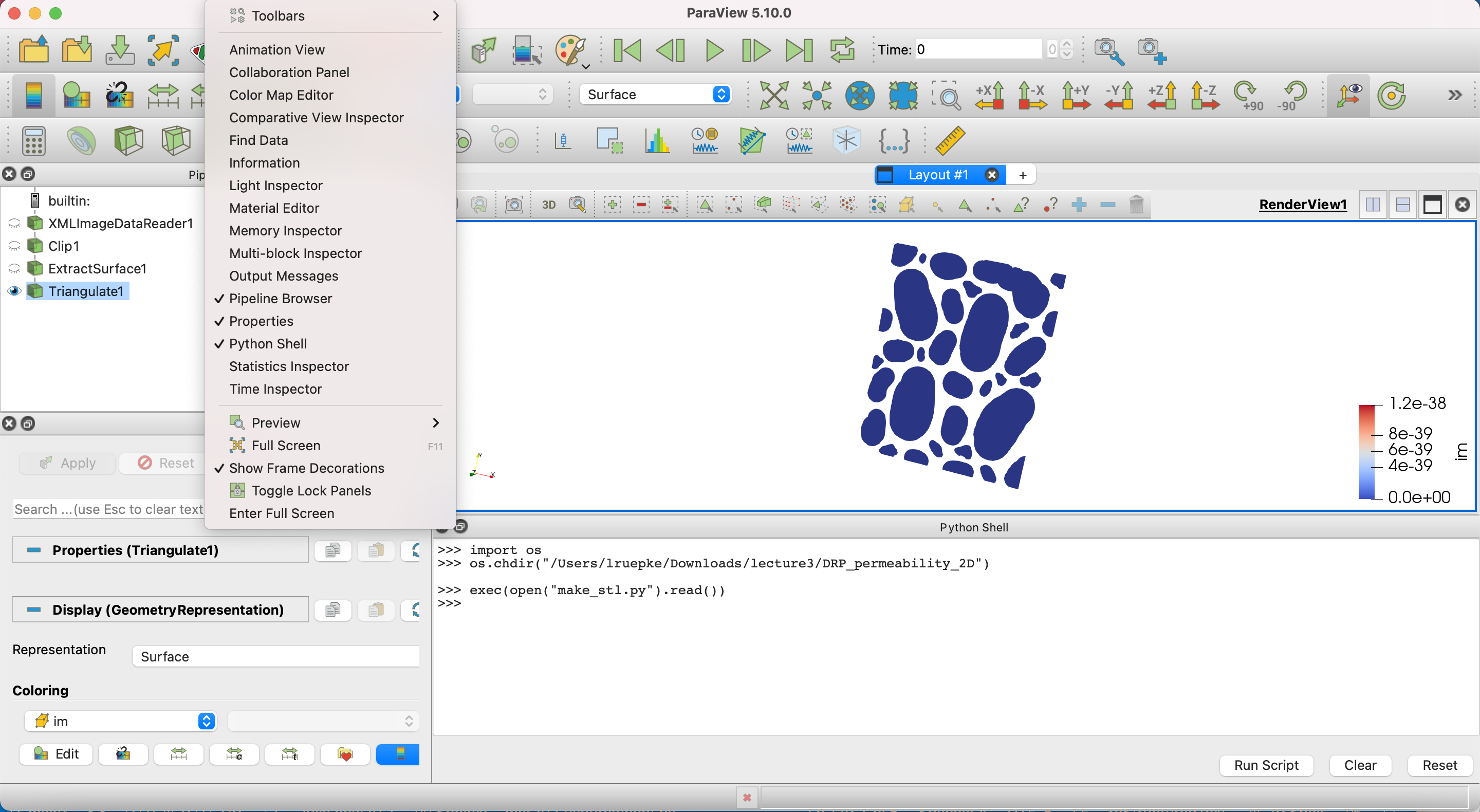
Fig. 14 The Python shell in ParaView.
OpenFOAM case
Making the mesh
Great, back to openfoam for the final mesh making! Making the mesh with SHM is a two-step process. First we make a standard blockMesh background mesh. This is, as usual, controlled by system/blockMeshDict:
 1/*--------------------------------*- C++ -*----------------------------------*\
 2=========                 |
 3\\      /  F ield         | OpenFOAM: The Open Source CFD Toolbox
 4 \\    /   O peration     | Website:  https://openfoam.org
 5  \\  /    A nd           | Version:  10
 6   \\/     M anipulation  |
 7\*---------------------------------------------------------------------------*/
 8FoamFile
 9{
10    version     2.0;
11    format      ascii;
12    class       dictionary;
13    object      blockMeshDict;
14}
15
16// * * * * * * * * * * * * * * * * * * * * * * * * * * * * * * * * * * * * * //
17
18convertToMeters 1;
19
20lx0 0;
21ly0 0;
22lz0 0;
23
24lx1 1196;
25ly1 1494;
26lz1 1;
27
28vertices
29(
30    ($lx0 $ly0 $lz0)   //0
31    ($lx1 $ly0 $lz0)   //1
32    ($lx1 $ly1 $lz0)   //2
33    ($lx0 $ly1 $lz0)   //3
34    ($lx0 $ly0 $lz1)   //4
35    ($lx1 $ly0 $lz1)   //5
36    ($lx1 $ly1 $lz1)   //6
37    ($lx0 $ly1 $lz1)   //7
38);
39
40blocks
41(
42    hex (0 1 2 3 4 5 6 7) (315 390 1) simpleGrading (1 1 1)
43);
44
45edges
46(
47);
48
49boundary
50(
51    top
52    {
53        type symmetryPlane;
54        faces
55        (
56            (7 6 3 2)
57        );
58    }
59
60    inlet
61    {
62        type wall;
63        faces
64        (
65            (0 4 7 3)
66        );
67    }
68
69    bottom
70    {
71        type symmetryPlane;
72        faces
73        (
74            (1 5 4 0)
75        );
76    }
77
78    outlet
79    {
80        type patch;
81        faces
82        (
83            (1 2 6 5)
84        );
85    }
86
87
88    frontAndBack
89    {
90        type patch;    // set to empty after snappyHexMesh (see run.sh)
91        faces
92        (
93            (0 3 2 1)
94            (4 5 6 7)
95        );
96    }
97);
Notice how we set the vertical and horizontal extents to 1196 and 1494, which is the pixel resolution of the image. We will scale it later to physical dimensions.
The mesh is only one cell thick, because we are doing a 2-D simulation. In 2-D cases, the front and back faces usually get the type empty. snappyHexMesh, however, only works on 3-D meshes, so we keep frontAndBack as a normal patch during meshing and change it to empty afterwards.
Now have a look at system/snappyHexMeshDict. We will not go into details here, just explore the general structure yourself if you are interested using the resources linked above.
Time to make the mesh! Run each of the steps below individually and check out the results in paraview.
blockMesh
snappyHexMesh -overwrite
foamDictionary constant/polyMesh/boundary -entry entry0/frontAndBack/type -set empty
checkMesh -allTopology -allGeometry
transformPoints "scale=(1e-6 1e-6 1e-6)"
The foamDictionary command sets the type of frontAndBack to empty in the final mesh (constant/polyMesh/boundary). The final conversion turns everything into micrometers (\(10^{-6}\) m). Check out the final mesh in paraview!
Note
checkMesh reports Failed 1 mesh checks for this mesh, because some cells cut by the grain surfaces have a small determinant. For this case, this is not a problem: the solver converges without difficulties.
Boundary conditions
Next we need to set boundary conditions. Our “rock” sample is 1196 and 1494 \(\mu m\) and we will apply a constant pressure drop of 1 Pa. We will further use openFOAM’s simpleFoam solver, which resolves incompressible steady-state flow. One important thing to remember is that openFOAM uses the kinematic pressure in incompressible simulations, which is the pressure divided by density. If we assume that water with a density of \(1000kg/m^3\) is flowing through our example, we will need to set a constant pressure value of \(P_{left}=0.001 m^2/s^2\). The pressure on the right-hand side will be set to zero.
Open the file 0/p in Visual Studio Code:
code 0/p
 1/*--------------------------------*- C++ -*----------------------------------*\
 2=========                 |
 3\\      /  F ield         | OpenFOAM: The Open Source CFD Toolbox
 4 \\    /   O peration     | Website:  https://openfoam.org
 5  \\  /    A nd           | Version:  10
 6   \\/     M anipulation  |
 7\*---------------------------------------------------------------------------*/
 8FoamFile
 9{
10    version     2.0;
11    format      ascii;
12    class       volScalarField;
13    location    "0";
14    object      p;
15}
16// * * * * * * * * * * * * * * * * * * * * * * * * * * * * * * * * * * * * * //
17
18dimensions      [0 2 -2 0 0 0 0];
19
20internalField   uniform 0;
21
22boundaryField
23{
24    top
25    {
26        type            symmetryPlane;
27    }
28    inlet
29    {
30        type            fixedValue;
31        value           uniform 0.001;
32    }
33    bottom
34    {
35        type            symmetryPlane;
36    }
37    outlet
38    {
39        type            fixedValue;
40        value           uniform 0;
41    }
42    solids
43    {
44        type            zeroGradient;
45    }
46    frontAndBack
47    {
48        type            empty;
49    }
50}
The boundary conditions are again set for the patches that were defined in the blockMeshDict. Notice how the sides have constant values. The top and bottom are symmetry planes and the internal boundaries with the solid grains get a zeroGradient condition. As we are performing a 2-D simulation, the frontAndBack faces are set to empty.
Remember that units are set by the dimensions keyword. The entries refer to the standard SI units [kg m s K mol A cd]. By having a 2 in the second and third column, we get the correct units for the kinematic pressure.
We also need to set boundary conditions for the velocity.
code 0/U
 1/*--------------------------------*- C++ -*----------------------------------*\
 2=========                 |
 3\\      /  F ield         | OpenFOAM: The Open Source CFD Toolbox
 4 \\    /   O peration     | Website:  https://openfoam.org
 5  \\  /    A nd           | Version:  10
 6   \\/     M anipulation  |
 7\*---------------------------------------------------------------------------*/
 8FoamFile
 9{
10    version     2.0;
11    format      ascii;
12    class       volVectorField;
13    location    "0";
14    object      U;
15}
16// * * * * * * * * * * * * * * * * * * * * * * * * * * * * * * * * * * * * * //
17
18dimensions      [0 1 -1 0 0 0 0];
19
20internalField   uniform (0 0 0);
21
22boundaryField
23{
24    top
25    {
26        type            symmetryPlane;
27    }
28    inlet
29    {
30        type            zeroGradient;
31    }
32    bottom
33    {
34        type            symmetryPlane;
35    }
36    outlet
37    {
38        type            zeroGradient;
39    }
40    solids
41    {
42        type            noSlip;
43    }
44    frontAndBack
45    {
46        type            empty;
47    }
48}
The top and bottom are again symmetry planes and the zeroGradient condition ensures that fluids can freely flow in and out. The contacts with the solid grains get noSlip, which makes the velocity go to zero; frontAndBack are again set to empty.
Transport properties
Final step is to set the remaining free parameter (viscosity) in equation (14).
code constant/transportProperties
 1/*--------------------------------*- C++ -*----------------------------------*\
 2=========                 |
 3\\      /  F ield         | OpenFOAM: The Open Source CFD Toolbox
 4 \\    /   O peration     | Website:  https://openfoam.org
 5  \\  /    A nd           | Version:  10
 6   \\/     M anipulation  |
 7\*---------------------------------------------------------------------------*/
 8FoamFile
 9{
10    version     2.0;
11    format      ascii;
12    class       dictionary;
13    object      transportProperties;
14}
15// * * * * * * * * * * * * * * * * * * * * * * * * * * * * * * * * * * * * * //
16
17transportModel  Newtonian;
18
19nu              [0 2 -1 0 0 0 0] 1e-06;
20
21// ************************************************************************* //
Again, in incompressible simulations (where we can divide the momentum balance equation by density) the kinematic viscosity is used, which has units of \(m^2/s\). The value of \(1e{-6} m^2/s\) with an assumed density of \(1000~kg/m^3\) corresponds to a dynamic viscosity of 1 mPa s - a typical value for water at room temperature.
Case control
Finally, we need to set some control parameters in system/controlDict. Open it and explore the values.
code system/controlDict
 1/*--------------------------------*- C++ -*----------------------------------*\
 2=========                 |
 3\\      /  F ield         | OpenFOAM: The Open Source CFD Toolbox
 4 \\    /   O peration     | Website:  https://openfoam.org
 5  \\  /    A nd           | Version:  10
 6   \\/     M anipulation  |
 7\*---------------------------------------------------------------------------*/
 8FoamFile
 9{
10    version     2.0;
11    format      ascii;
12    class       dictionary;
13    object      controlDict;
14}
15// * * * * * * * * * * * * * * * * * * * * * * * * * * * * * * * * * * * * * //
16
17application     simpleFoam;
18
19startFrom       startTime;
20
21startTime       0;
22
23stopAt          endTime;
24
25endTime         1500;
26
27deltaT          1;
28
29writeControl    timeStep;
30
31writeInterval   1500;
32
33purgeWrite      0;
34
35writeFormat     ascii;
36
37writePrecision  9;
38
39writeCompression off;
40
41timeFormat      general;
42
43timePrecision   6;
44
45runTimeModifiable true;
The solver is a steady-state solver, so the settings are simpler than in transient simulations: the “time” is just the iteration counter.
Running the case
Now we are finally ready to run the case! Type this into a terminal in the container:
./run.sh
or, if you did the steps above by hand:
simpleFoam
Notice how one new directory is appearing, which contains the steady-state solution. Check that the solution has converged by looking at the log.simpleFoam file.
tail -15 log.simpleFoam

Time = 537

smoothSolver:  Solving for Ux, Initial residual = 9.48718063e-10, Final residual = 9.48718063e-10, No Iterations 0
smoothSolver:  Solving for Uy, Initial residual = 9.93804308e-10, Final residual = 9.93804308e-10, No Iterations 0
GAMG:  Solving for p, Initial residual = 9.71539045e-09, Final residual = 9.71539045e-09, No Iterations 0
time step continuity errors : sum local = 7.1290424e-07, global = -1.41776643e-07, cumulative = 3.8954571
ExecutionTime = 30.24 s  ClockTime = 30 s


SIMPLE solution converged in 537 iterations

End
And explore the solution in Paraview!
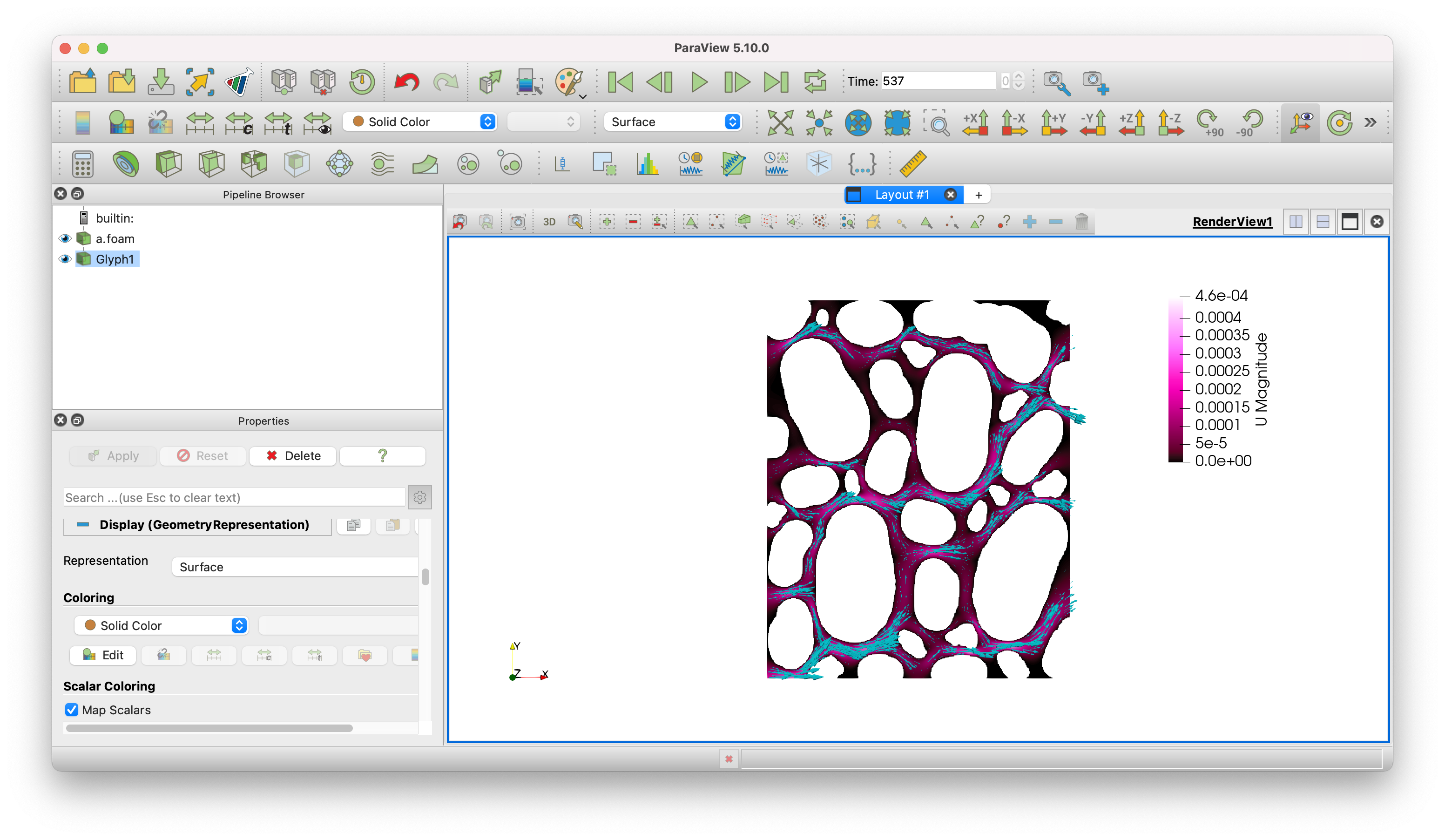
Fig. 15 Predicted velocity field.
Post-processing / Effective permeability
Time to get back to our initial objective. What is the predicted permeability of our sample? We need to postprocess our solution and solve equation (16), which requires a few intermediate steps. First, we need to compute the cell volumes, so that we can integrate the velocity over the total volume. Here, openFOAM’s postProcess functionality comes in handy. Just do this:
postProcess -func writeCellVolumes
This will create a new variable \(V\) in the output directories, which is the volume of each cell. Next we can save the full solution as a vtk file, so that we can postprocess it with python.
foamToVTK -useTimeName -latestTime -poly
Check that a new VTK directory was created. The file name contains the name of the case folder and the iteration, e.g. VTK/DRP_permeability_2D_537.vtk; adjust the name in the script below if your folder name or the number of iterations differ. Now we are ready for some more fancy post-processing using python.
Here is an example script for computing permeability. You can turn it into a jupyter notebook or save it as a .py file into your case directory and run it from there.
import vtk
import numpy as np
from vtk.util import numpy_support as VN
import matplotlib.pyplot as plt

# load VTK data
vtkFile = 'VTK/DRP_permeability_2D_537.vtk'
reader = vtk.vtkUnstructuredGridReader()
reader.SetFileName(vtkFile)
reader.ReadAllScalarsOn()
reader.ReadAllVectorsOn()
reader.Update()
data = reader.GetOutput()


# extract velocity arrays
Vcells = VN.vtk_to_numpy(data.GetCellData().GetArray('V'))
U = VN.vtk_to_numpy(data.GetCellData().GetArray('U'))
Umag = np.sqrt(U[:,0]**2+U[:,1]**2+U[:,2]**2)
Ux = U[:,0]
Uy = U[:,1]
Uz = U[:,2]

# calculate volume fluxes
qx = []
qy = []
for c in range(len(Vcells)):
    q1 = Vcells[c] * Ux[c]
    q2 = Vcells[c] * Uy[c]
    qx.append(q1)
    qy.append(q2)

# simulation parameters
DP = 1                       # pressure drop [Pa]
nu = 1e-06                   # kinematic viscosity [m²/s]
rho = 1000                   # density [kg/m³]
mu = nu * rho                # dynamic viscosity [kg/(m*s)]
dx = 0.001196                # model length x [m]
dy = 0.001494                # model width y [m]
dz = 1e-6                    # model thickness z [m]
A = dy * dz
V = dx * A

# calculate Darcy velocity
U_Darcy_x = np.sum(qx)/V

kxx = mu * dx * U_Darcy_x/DP

print('Bulk permeability: %5.3e m2' % kxx)
We made it! \(2.71e^{-11} m^2\) is our predicted effective permeability of our sample.